


Thermal mass flow meters are perfectly suited for measuring clean, dry compressed air and inert gases, where accuracy on smaller pipe sizing is important. Compressed Air Alliance offers two types of thermal mass flow meters – insertion flow meter and inline (or in-line) flow meter.
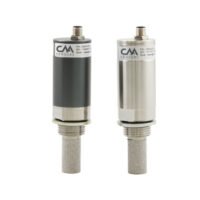
Insertion flow meters
- Insertion flow sensors are inserted into the pipe through a valve. They can be inserted under pressure so you don’t need to turn off your compressed air system during installation.
- Suitable for pipes from DN20 to DN600
- Insertion flow meters are best used for permanent and temporary installations.
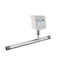
Inline Flow Meters
- Inline flow sensors include a section of pipe as part of the flow meter. You will need to turn off compressed air and cut a section of pipe out to install the inline flow meter.
- For information on Inline Flow Meters, refer to Inline Flow Meter page.
Both of Compressed Air Alliance’s thermal mass flow meters (inline and insertion style) have a streamlined sensor tip which ensures minimal impact on gas flow while maintaining accuracy over a wide flow range.
Important
- The sensor must be installed (i) in dry gas, (ii) at 90° to the pipe and (iii) away from bends, edges, seams, changes in pipe size and other obstructions,
- Incorrect wiring or installation can give false readings, damage the sensor and void the warranty. If you aren’t sure how to install or wire the sensor, please contact us. Full installation and wiring instructions are available in the User Manual.
Thermal Mass Meter comes with:
- Flow meter
- M12 connector (data cable optional)
- Calibration certificate
- User Manual
- 12 month warranty
Warranty & Calibration
12 month warranty
Calibration is recommended every 2 years (provided the sensor is not exposed to relative humidity above 85%).
Annual calibration is required if the sensor is exposed to relative humidity above 85%.
Accessories
Accessories such as mechanical and electrical fittings are available on the Accessories page.
Other Information
Part Numbers: FLT100001, FLT200001, FLT100011, FLT200011, FLT100101, FLT200101, FLT100111, FLT200111, FLT110001, FLT210001, FLT110011, FLT210011, FLT110101, FLT210101, FLT110111, FLT210111
Please refer to our Terms and Conditions of Sale.